




Unlocking late-model Bosch MD1 ECUs previously required voltage glitching, which meant removing small surface-mount resistors directly from the circuit board. Magic Motorsport Flex software updates this procedure using Korhex and Electromagnetic Fault Injection (EMFI).
Here is a step-by-step walk-through using a locked 2022 Peugeot/Citroën MD1CS003 (1.5 BlueHDi) ECU as an example.
Required Hardware
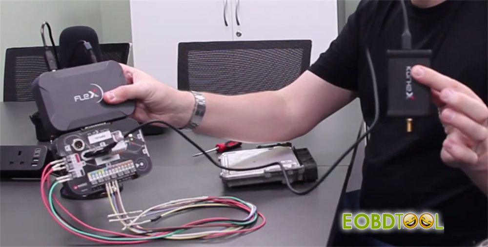
- Magic Motorsport Flex Full Master 5 M/Slave FLS0.5Sor Flex with FLS0.20M/S (includes Flex box)
- Flex software 23.0.0 or higher version (such as 8.24.1.0)
- Magic Motorsport Korhex Tool Kit(Korhex unit, adapter board, USB cable, probe antennas, power supply)
- Processor Alignment Mask (F Mask)
- Articulating support arm
Step-by-Step Walkthrough
Step 1: Check Wiring Diagram
Open Flex software, click “Vehicle list” on the main menu
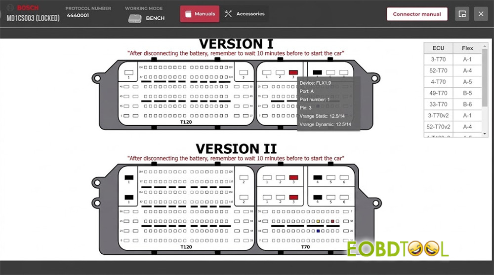
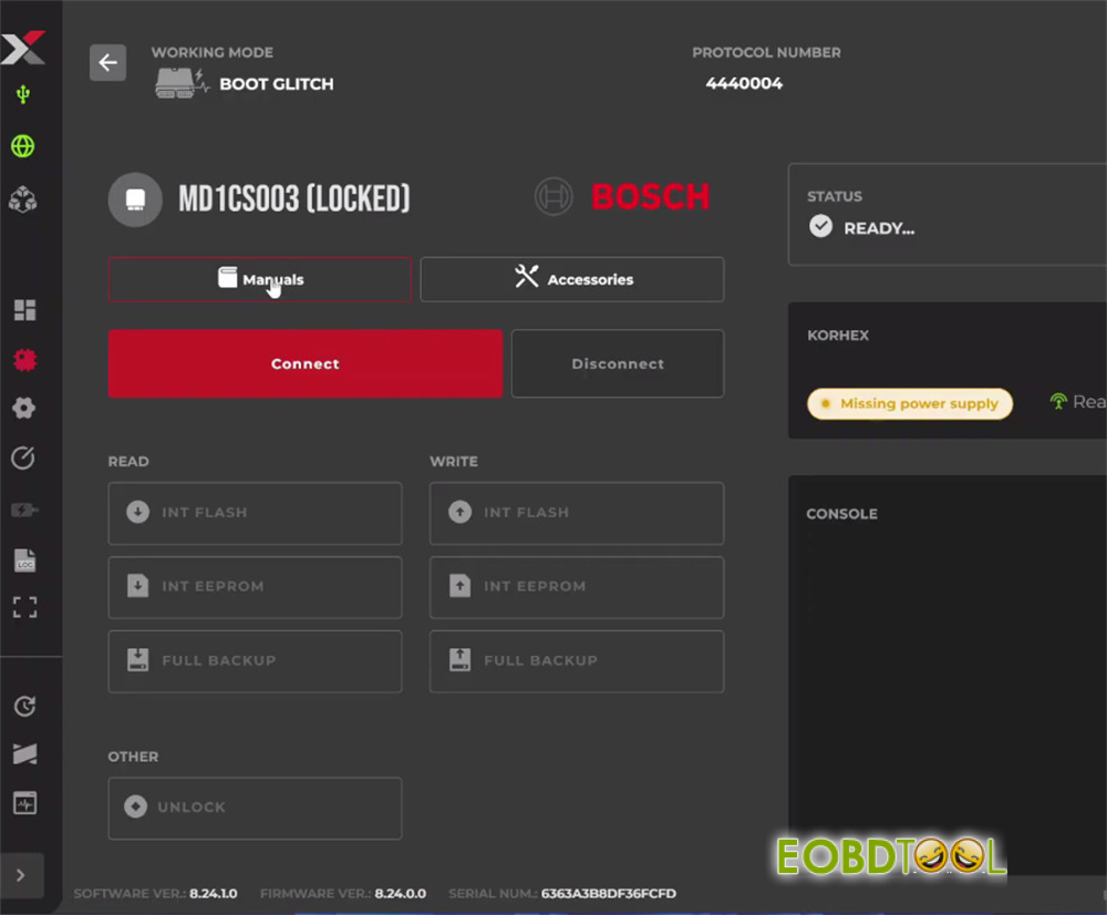
Input md1cs003 to locate Peugeot BOSCH MD1CS003 [Locked]
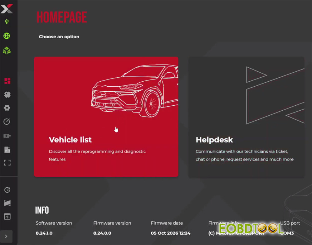
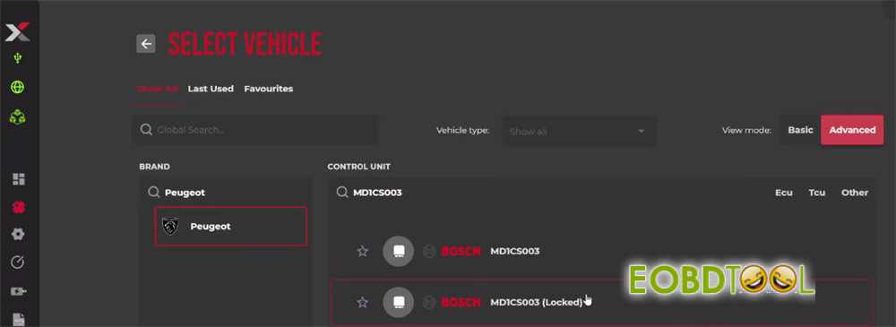
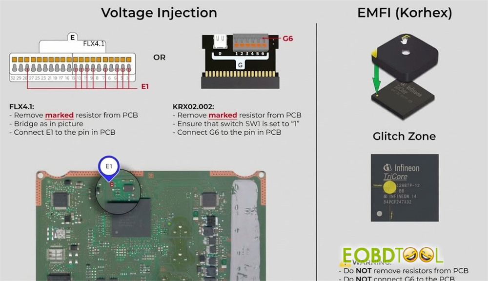
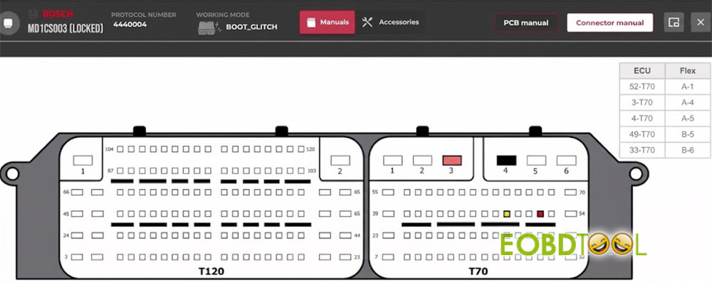
Click Manuals to check the PCB and connector manual
Step 2: Position the Injector
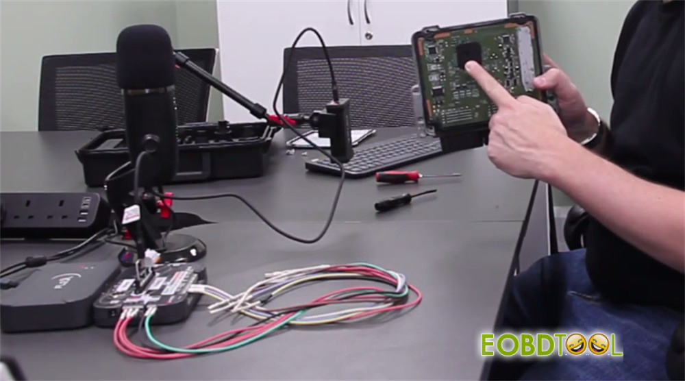
Open the ECU cover to expose the central microprocessor.
Place the matching alignment mask (F Mask) directly over the chip.
Mount Korhex unit onto an adjustable arm (a standard phone mount works well) so the antenna probe sits straight at a 90°angle through the mask hole.
Step 3: Connect Harness
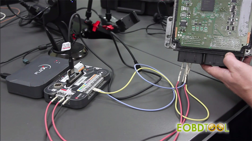
Connect Flexbox harness to the ECU pins according to the PCB manual:
- Primary power cable to A4
- Secondary power cable to A1
- Ground cable to GND
- CAN bus lines to B5and B6
All circuit board resistors remain in place, and pin G6 is left unconnected.
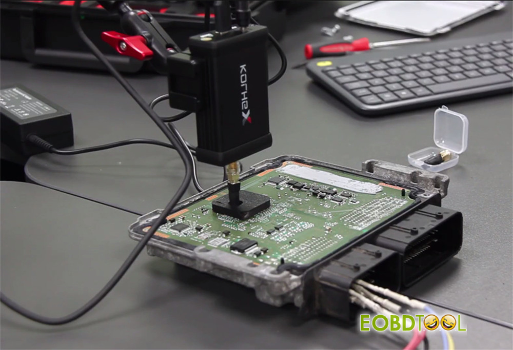
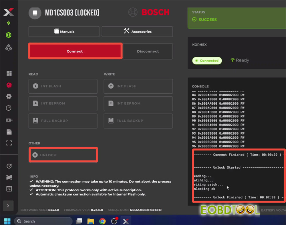
Step 4: Unlock ECU (Boot Glitch)
Select the Locked Boot Glitch protocol in the Flex software and initiate the connection.
Korhex Boot Glitch MCU Tool delivers precise electromagnetic pulses to disrupt the processor briefly.
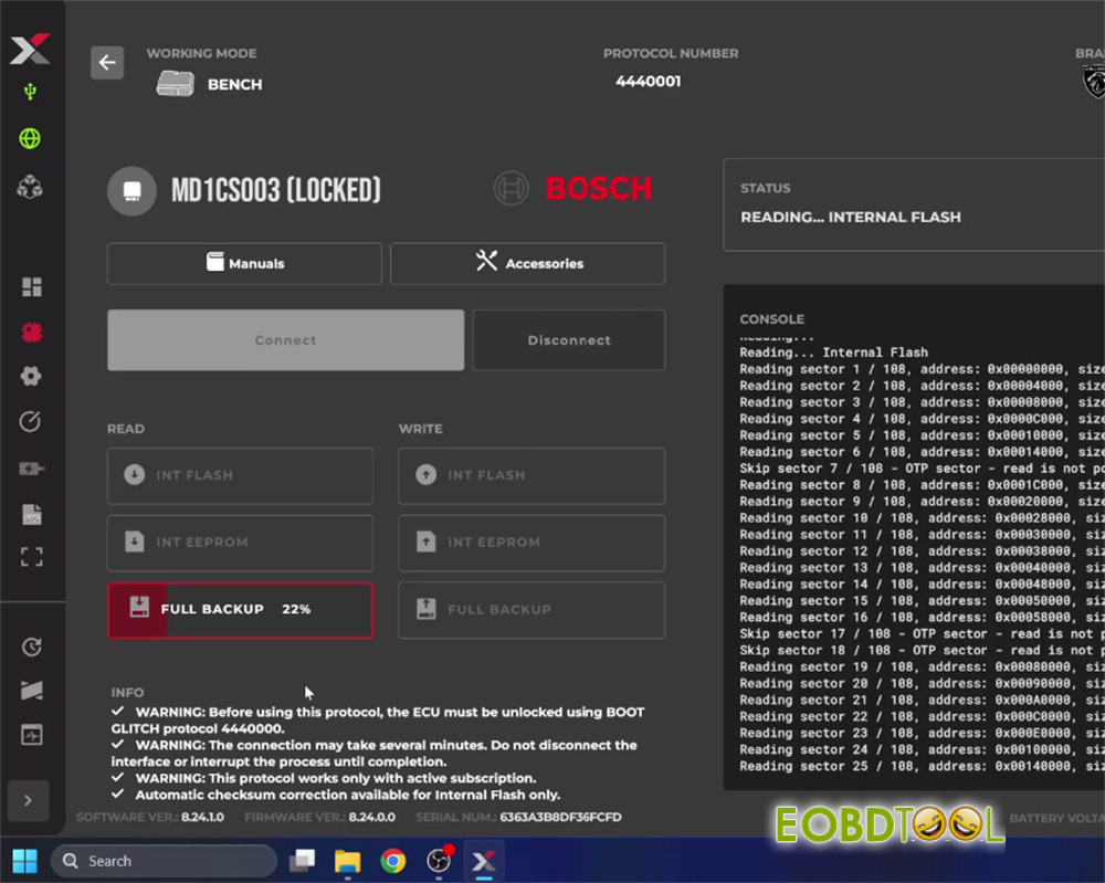
The software then creates a backup read and writes the unlock patch automatically.
Step 5: Read and Write ECU (Bench Mode)
Once unlocked, remove Korhex adapter from the work area.
To read or write the ECU on the bench:
- Swap the power connections on the Flexbox: move A4 to A1, and A1 to A4.
- Keep the ground and CAN bus wires connected as they are.
You can now connect to the ECU using standard bench protocols.